To configure an ip address: ifconfig eth0 <ip address> netmask <mask> up
To confirm the ip address on the interface: ifconfig
To configure the gateway ip address: route add default gw <gateway ip address>
To confirm the default gateway ip: route
To enable DHCP for an interface: udchpc <interface>
ctrl+c or command+c on MAC to cancel a ping or traceroute command
If a username and password is requested to login into the linux PC host within the topology, use: gns3/gns3 or tc/tc
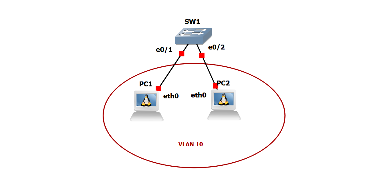
Create VLAN 10 and name the vlan DATA
- Verify the VLAN was created
Configure PC1 and PC2 as access ports and assign them to VLAN 10
- Verify the ports are in VLAN 10 as well as the ports are access-ports
Configure PC1 with ip address 192.168.10.11/24
Configure PC2 with ip address 192.168.10.12/24
Test connectivity between PC1 and PC2 (Each device should be able to ping the other)
configure terminal
vlan 10
name DATA
exit
interface range e0/1-2
switchport mode access
switchport access vlan 10
exit
end
show vlan
show vlan brief
show interface status
show interface switchport
show run
show run int eth0/1
show run int eth0/2
ifconfig eth0 192.168.10.11 netmask 255.255.255.0 up
ifconfig
ifconfig eth0 192.168.10.12 netmask 255.255.255.0 up
ifconfig
For this lab, you were first tasked with creating “VLAN 10”. To accomplish this, you first must go into configuration terminal mode SW(config)# from privilege exec mode SW#. From there, you must create VLAN 10 using the VLAN command keyword followed by the VLAN number you want to create.
The next step was to name the VLAN “DATA”. To accomplish this, we must use the keyword “name“ followed by the name we would like to assign to the VLAN. The next thing we were asked to do is verify the VLAN was created. We can accomplish this in three ways. The first and second way would be to use the show VLAN (not case sensitive) or show VLAN brief commands from user exec mode denote by > after the name of the device, for instance SW>, or from privilege exec mode respectively. The third way would be to use the do command followed by either show VLAN or show VLAN brief from configuration mode or any sub-configuration modes, for instance under SW(config-if)# for interface configuration mode you can use do show VLAN. The do command can be used for any show commands when in configuration mode or any of its sub-configuration modes.
Once the VLAN has been successfully created, you will be able to see the VLAN in the output using either the show VLAN or show VLAN Brief commands. The second task we were asked to complete was to configure the ports leading to PC1 and PC2 as access ports and then assign them to VLAN 10. We can accomplish this task by using the interface range command in configuration mode. The interface range command allows us to configure multiple interfaces at the same time. This command is best used when the exact same information needs to be applied to multiple interfaces. If any of the information differs in the slightest, then the interface range command should not be used; and you should configure the ports independently. To accomplish this task, in configuration mode, SW(conf)#, we use the interface range e0/1-2 command to enter into the interface range sub-configuration mode, SW(conf-range-if)#, to configure the interfaces. From here, we issue the switchport mode access command to tell the switch we want to hard set these interfaces to static access mode.
Next, we use the command switchport access VLAN 10. This tells the switch that we want to associate the port with VLAN 10, and only VLAN 10 when it is operating as an access port.
Next, we were asked to verify that the switch ports for PC1 and PC2 were access ports and assigned to VLAN 10. We can accomplish this with several show command. The show commands we can use to accomplish this goal are: show VLAN, show VLAN brief, show interface status, show interface switchport
Once we issue the show run command, we will see in the output allow of the configuration for that particular interface. Under the interface for e0/1 and e0/2 using the command show run interface e0/1 and show run interface e0/2 respectively, we should see the commands, switchport mode access, and switchport access VLAN 10. The third task we were ask to perform was to configure the IP address 192.168.10.11/24 on PC1.
To accomplish this, we will issue the following command on the command line for PC1: ifconfig eth0 192.168.10.11 netmask 255.255.255.0 up.
Next we will verify the port took the IP address and mask by issuing the follow command: ifconfig Under interface eth0 we are looking for IP address 192.168.10.11, mask 255.255.255.0 and the keyword “up” We then will repeat the steps on PC2 but just changing the IP address to the correct noted in the task steps. Once both of the PC’s have their IP address, we will then move to the next step by verifying that both of the PC’s can ping each other. On PC1, we issue the command ping 192.168.10.12 from the command line. We should get several ping replies from PC2 at this point. To cancel the ping process, hold ctrl+c or command+c on MAC OS to cancel the ping request.
Next, we move over to PC2 and issue the ping command towards PC1: ping 192.168.10.11. At this point we should have full connectivity between PC1 and PC2.
And with that, the lab tasks have been completed.